How to Power an Electrified Railway, From the 1930s To Present
This article originally appeared in The Reed College Quest.
Among the things the Northeastern United States is known for is its electric high-speed railway network, something no other part of the country or the entirety of North America has (at least until California High-Speed Rail is completed). High-speed trains run on the Northeast Corridor and cover its 457-mile length from Boston to Washington via New York City in roughly 6.75 hours. The Keystone Corridor runs from Philadelphia to Pittsburg and supports higher-speed operation (though it isn't a true high-speed route). The eastern section is electrified and owned by Amtrak, while the western section is not.
This network is more the result of circumstance than the result of intentional planning, having been created from the once-flagship passenger mainlines of three Northeastern railways that had since become redundant following the decline in the American railway network.
As such, while these lines have received substantial amounts of maintenance and upgrades, they still retain aspects of their past. One such aspect is in how the lines are electrified. In particular, the southern section of the Northeast Corridor—connecting New York City to Washington, DC—and the eastern section of the Keystone Corridor—connecting Philadelphia, PA to Harrisburg, PA—retains in large part its original electrification system, constructed in the 1920s-1930s by the Pennsylvania Railroad (PRR).
Electrifying a railway line today is relatively straightforward, owing to widespread electrification of the country and advances in railway technology. But how do you do that in the 1930s, without any of that? The PRR just built their own electrical grid, running at an alternating current frequency of 25 Hz (which was better for the traction motors of that time). Because this electrical grid runs at a different frequency than the modern North American electrical grid does, the network cannot be directly connected to the broader electrical grid. Instead, it receives power through various converter stations of various vintages, from Safe Harbor Dam on the Susquehanna river, and formerly from dedicated coal power stations as well.
This network needs its own means of control, so several Power Director Centers and one Load Dispatch Center were built along with it. Power directors controlled the flow of power from the transmission network into the overhead wires that actually delivered power to trains. Load dispatchers were in charge of the entire transmission network and coordinated operation of the network's various power sources. When this network was built in the 1930s, it had to operate without the benefit of modern computer networks and remote control equipment. The power directors and load dispatchers instead had to telephone staff at or near each substation to query status information and make requests.
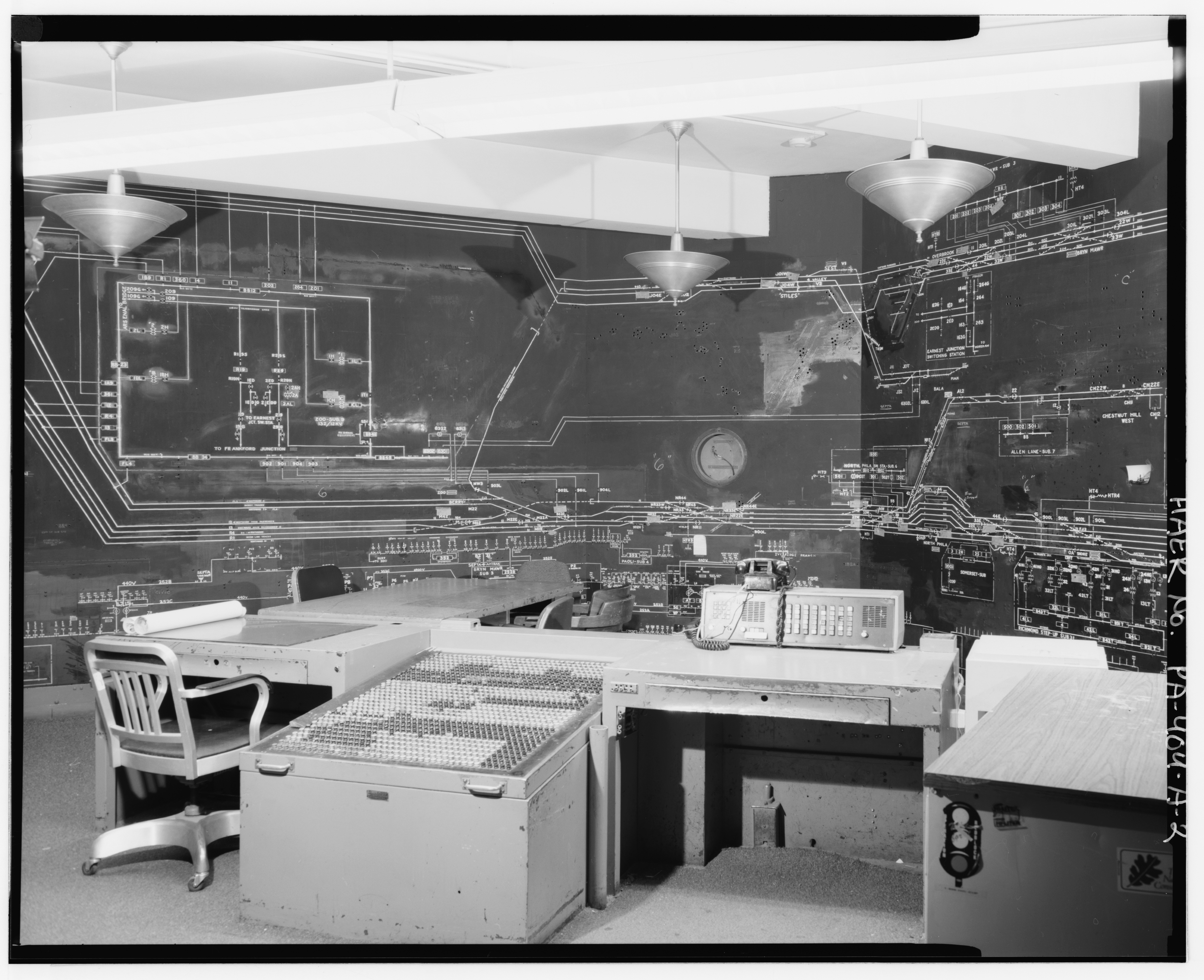
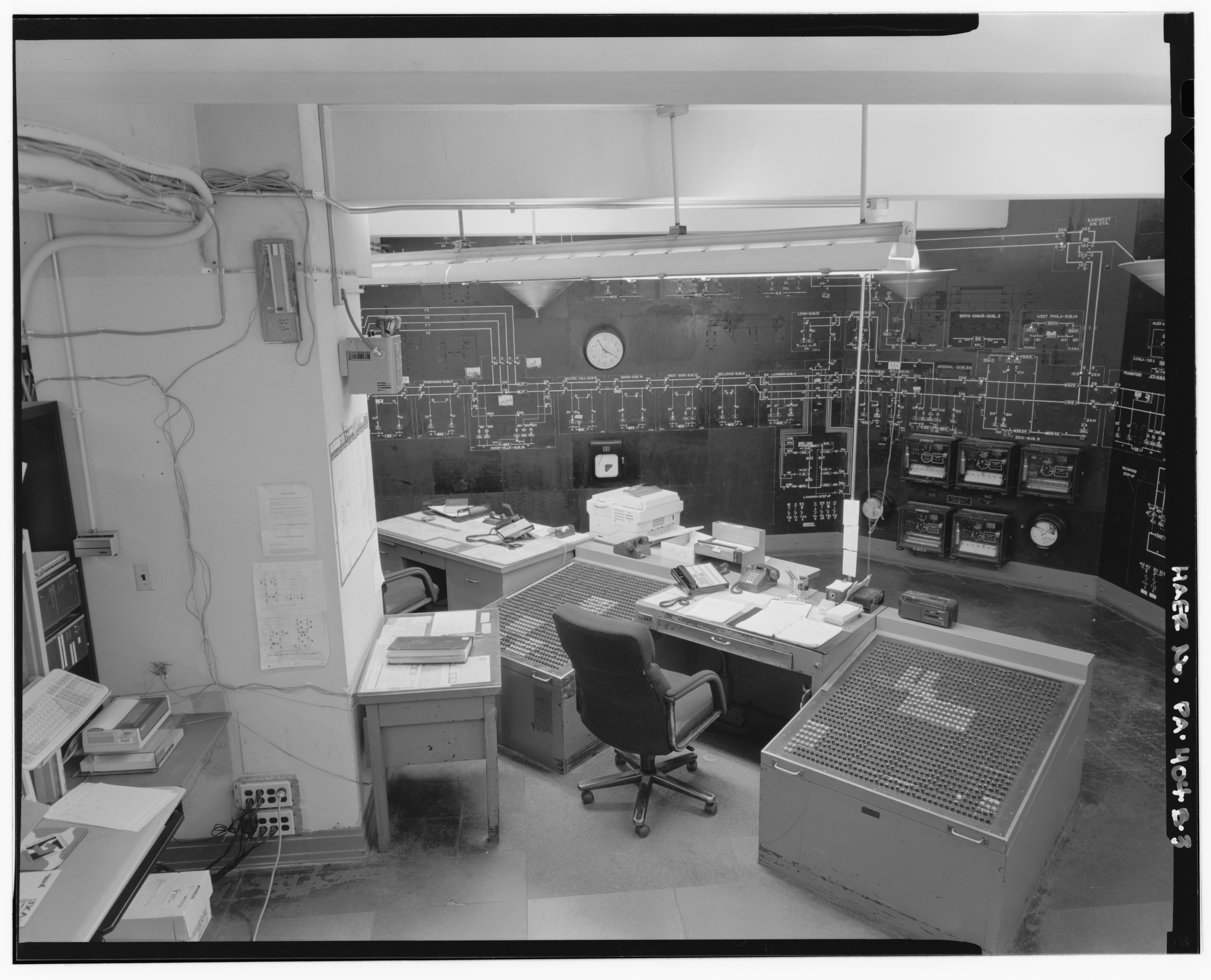
To keep the power directors and load dispatchers aware of the current state of the network, large model boards showed the network in schematic form, and used small lamps to denote the status of each switch and circuit breaker. When someone learned of or requested a change in the network, they would manually push or pull a button located near their desk. This would update the model board appropriately. Pictured below is part of the Philadelphia Power Director Center. While this control room is no longer in service, its history sheds light on the engineering challenges involved in building and operating this electrical grid.

The board contains both a diagram of the tracks in the Center's control area and a diagram of the transmission lines and substations used to power that area. In the end, Amtrak built the Central Electrification and Traffic Control (CETC) system to remotely control their signaling and power equipment from Philadelphia. This Power Director Center in Philadelphia was the second-to-last cut over to CETC. The last Power Director Center was in Harrisburg, PA, and remained in operation until 2012 with mostly original equipment.

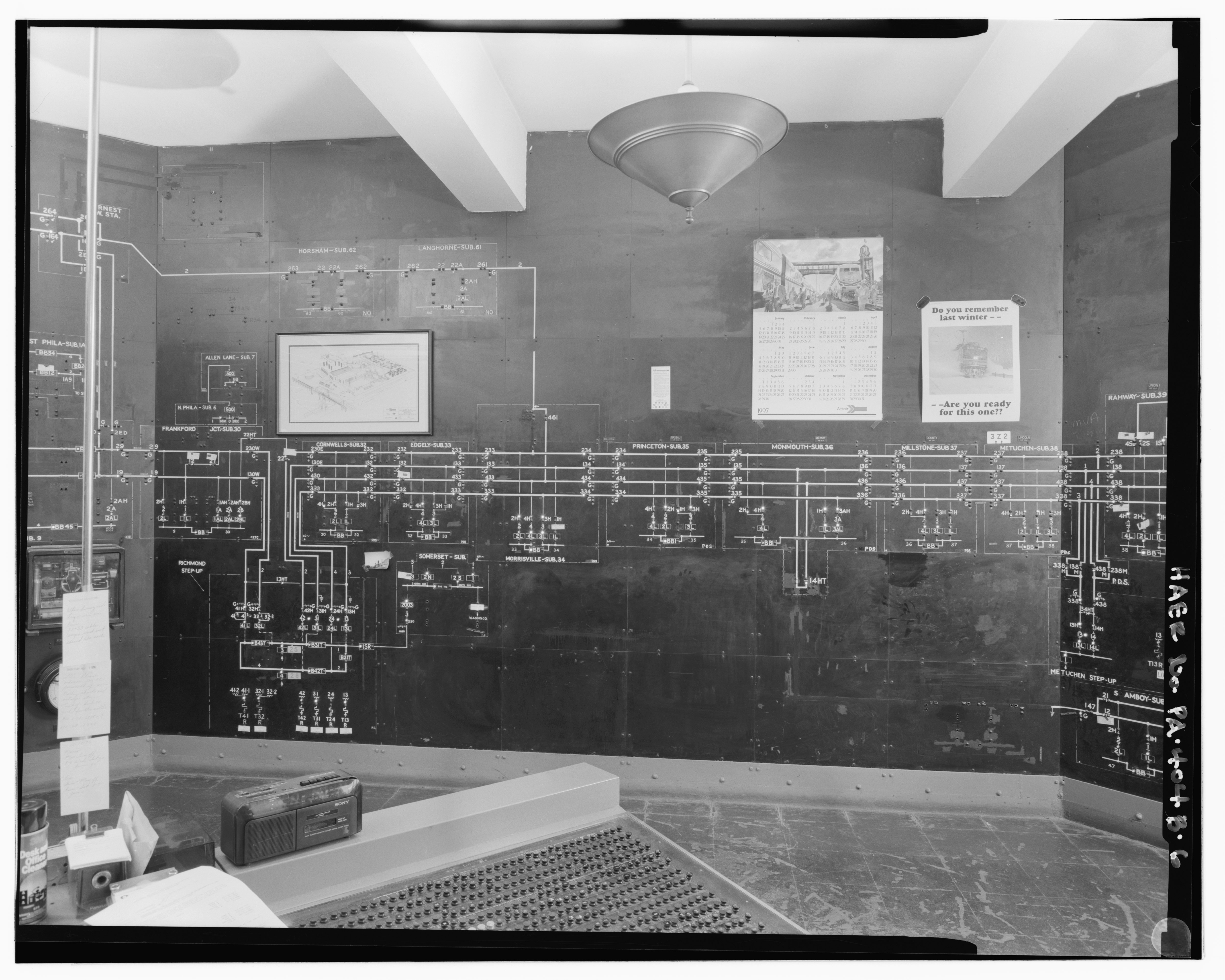
Load dispatchers ensure that the transmission network functions properly, that electrical generation and conversion into the network matches the load on the network exactly, and plans transmission outages and work to ensure worker safety and system reliability. On the wall in this image is a model board showing the entire transmission network; as with the Power Director Center, this model board is a visual aid to the load dispatchers that is used to display the current status of field equipment. The board uses a "single-line diagram" format, with each circuit (which could contain multiple wires) represented as one line. Switches are displayed as lines with lights around them, breakers are displayed as boxes, and transformers are displayed as numbers surrounded by lines orthogonal to the circuit lines entering and leaving them. Lamps use the traditional electric utility convention where a red lamp indicates that a switch/breaker is closed and a green lamp indicates that a switch/breaker is open. Various lines, switches, and substations have been painted out or covered in black tape, a reflection of the unfortunate loss or de-electrification of some railway lines, especially electrified freight lines.

Also of note on the Load Dispatch Center's model board is the calendar for 1997, displaying a picture of the Oakland—Jack London Square station, opened in 1995 to replace the earthquake-damaged 16th Street Station. I remember both stations well from my time living in Oakland: Jack London Square as the station I would catch trains at or pass through, and 16th Street Station as a ghostly, trackless relic near a freeway that I seldom used. On the right is a GE P42DC-type passenger locomotive, which would have been new in that time. There is also a poster admonishing load dispatchers with the phrase "DO YOU REMEMBER LAST WINTER—ARE YOU READY FOR THIS ONE??" with a photo of an Amtrak AEM-7 electric locomotive in the snow. I do not know of any particular 1990s winter disaster or impact to train service that would have prompted the poster, but its sentiment is one that seems particularly relevant to Reed College in the present day! The Load Dispatch Center was decommissioned shortly after these photos were taken in 1997, replaced by a contemporary computer-based energy management system. As with the Power Director Center, the complexity of this traction power network, with its awe-inspiring scale, is clearly laid out as a testament to the engineering and systems required to electrify a railway.
Let's now discuss what the diagrams mean. Each substation—a part of the network that supplies a section of track with power—has a box drawn around its components and a label and number associated with it. Consider Princeton #35 substation as an example of a typical substation. Four 138 kV (kilovolt) transmission lines enter on the left and right. These efficiently transmit power across the network. Switches 134, 234, 334, 434, 135, 235, 335, and 535 are used to allow maintenance to be performed on the lines or substation. Switches 4H, 2H,1H, and 3H are connected to the transmission line, and feed transformers 4, 2, and 3. These transformers transform the 138 kV power on the transmission lines to the 12 kV power supplied to the trains themselves. Switch 1H once supplied a transformer that has now been removed and painted out; now, it provides an alternate feed for transformer 3 from transmission line 1 instead of from line 3. Its symbol is different to reflect the fact that it is normally open, while other switches are normally closed. Breakers 4L, 2L, and 3L protect the transformers from short-circuits and overloads. From there, transformers 4 and 2 feed bus 34, while 3 feeds bus 35. These buses are connected to the overhead wires above the track through wires not pictured on the diagram. Bus 34 supplies power to overhead wires south of the substation, while bus 35 supplies power to overhead wires north of the substation. The bus tie breaker, BB1, is normally closed but can open to isolate a section of overhead wire for maintenance or due to a fault.
While both of these control rooms were replaced with more modern equipment and are, as far as the author can tell, entirely dismantled, they were once a deeply tangible representation of what it took to build an electric railway network nearly a century ago. Today, electric rail travel is a uniquely efficient and environmentally friendly means of transportation, and has a safety record vastly better than that of car travel. For journeys of the right length, high speed rail can even compete favorably on time and convenience with airline travel.